RACB Motor
A High Speed Motor is designed to rotate far faster than a conventional electric motor. In many industrial systems, it drives a spindle, compressor, pump, or small turbine. Its compact body may spin at tens of thousands of revolutions per minute. That number sounds impressive, but speed alone does not guarantee better performance.
This article explains what a High Speed Motor is and how it works. It examines the interaction between electromagnetic fields, rotor balance, bearings, cooling systems, and electronic controllers. For example, a motor running at 30,000 rpm can generate noticeable heat within seconds if airflow is restricted. Even a slight rotor imbalance may create vibration, noise, and premature bearing wear.
The design is demanding.
Engineers must match torque, voltage, frequency, and load requirements carefully. Permanent magnet motors often provide high power density, while induction designs can offer durability in demanding environments. However, each choice involves trade-offs. A motor that performs well at light load may struggle during acceleration or sudden mechanical resistance. This is where practical testing matters more than attractive specifications.
The following sections will discuss the main components, operating principles, control methods, efficiency factors, and safety considerations of high-speed operation. Measurements such as temperature, vibration, current, and shaft speed help verify reliable performance. Some explanations may simplify complex electromagnetic behavior, because real systems rarely behave perfectly. That limitation deserves attention, not concealment. Understanding these details helps readers select, install, and maintain a High Speed Motor with greater confidence.
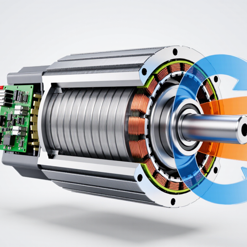
A high-speed motor is an electric motor designed to rotate faster than conventional industrial motors. There is no universal speed limit. In practice, engineers often describe motors above 10,000 revolutions per minute as high-speed units. Some systems exceed 100,000 revolutions per minute. The correct range depends on the application, power rating, and mechanical design.
Its operation remains familiar. An inverter sends controlled electrical current into the stator windings. This creates a rotating magnetic field. The rotor follows that field and produces torque. Higher frequency increases rotational speed. However, speed adds difficult engineering problems. Rotor balance must be extremely precise. Bearings face greater loads. Cooling channels must remove heat quickly. Even a small manufacturing error can cause vibration, noise, or early failure. That detail is often underestimated.
High-speed motors can reduce equipment size and improve power density. They are used in compressors, machine tools, pumps, turbines, and electric mobility systems. The International Energy Agency has reported that electric motor systems consume about 46% of global electricity. This figure shows why efficiency matters beyond a single machine. Yet high speed does not automatically mean better performance. Friction, windage, inverter losses, and cooling demand may increase. Engineers should measure the complete system, not only the motor’s rated efficiency. In my view, the most reliable design is rarely the fastest one. It is the one that maintains stable temperature, vibration, and output across real operating conditions.
It is an electric motor built for unusually fast rotation. Many engineers use 10,000 revolutions per minute as a practical reference. Some systems exceed 100,000 revolutions per minute. The exact limit depends on design, power, and application.
An inverter sends controlled current through stator windings. The windings create a rotating magnetic field. The rotor follows that field and produces torque. Higher electrical frequency usually creates higher rotational speed.
Important parts include the stator, rotor, bearings, inverter, sensors, and cooling jacket. Copper windings guide electrical energy through the stator. The rotor includes a shaft, magnetic elements, and protective support. Bearings carry the shaft under heat and centrifugal stress. Small details matter.
A tiny imbalance can create strong vibration at high speed. The vibration may increase noise, wear, and mechanical stress. It can also cause early failure. Accurate balancing and alignment are essential. A small error becomes a large problem.
They operate compressors, pumps, machine tools, turbines, and electric mobility systems. A compressor may adjust output quickly when pressure changes. A machine tool may need compact power and rapid response. Their usefulness depends on the complete operating environment.
They can deliver substantial power from a smaller, lighter package. This may save installation space and reduce transmission losses. Fast acceleration can improve process response. However, faster does not automatically mean better. That assumption needs checking.
Friction, windage, electrical losses, and cooling demands can increase. Bearings may experience heavy loads and higher temperatures. Noise and rotor containment also require careful engineering. Light-load operation may reduce efficiency. Some designs look excellent on paper but perform poorly in dusty facilities.
Monitor vibration trends instead of checking isolated readings. Watch temperature changes near bearings and insulation. Keep cables short and properly shielded when practical. Maintain accurate alignment and suitable lubrication. Never dismiss a small temperature rise. It may indicate a larger mechanical issue.
A High Speed Motor is an electric machine designed to operate at much higher rotational speeds than conventional motors, allowing it to deliver rapid, precise motion in a compact form. It generates torque when electromagnetic forces act between the stator and rotor, while the motor’s shaft transfers this rotational energy to connected equipment. Key internal components typically include windings, a rotor, bearings, a housing, sensors, and an electronic controller. Each part must be carefully balanced and engineered to withstand vibration, heat, and mechanical stress.
Speed control systems regulate electrical input to adjust rotation smoothly and maintain stable performance under changing loads. Because high-speed operation produces significant heat, cooling methods such as airflow, liquid circulation, or heat-conducting structures are often required. High-speed motors are valued for their efficiency, small size, quick response, and suitability for pumps, compressors, machine tools, and automated equipment. However, they may involve higher manufacturing costs, stricter maintenance requirements, noise, vibration, and reduced durability if cooling or balance is inadequate.