RACB Motor RACB Motor

What Is a Precision Gear Motor and How Does It Work?

Time:2026-10-10 Author:Ethan
0%

A Precision Gear Motor combines an electric motor with a gearbox to deliver controlled speed, torque, and positioning. The motor creates rotational force. The gear train reduces speed and increases usable torque. In a compact conveyor, for example, the motor may spin rapidly while the output shaft turns slowly enough to move products without sudden jolts.

This technology matters because motor systems consume substantial industrial energy. The International Energy Agency reports that electric motor systems represent roughly half of global electricity consumption. Better control, efficient transmission, and correct sizing can therefore influence operating costs. The International Federation of Robotics recorded 541,302 industrial robot installations worldwide in 2023. That figure shows why repeatable motion and compact drive systems remain important across factories, packaging lines, and laboratory equipment.

A Precision Gear Motor is not defined by accuracy alone. Backlash, gear quality, encoder resolution, bearing stiffness, thermal limits, and load variation all affect real performance. ISO 286-1 provides a useful framework for dimensional tolerances, but it does not guarantee perfect motion in every application. The distinction is not always tidy. A motor may meet a catalog specification yet perform poorly when exposed to vibration, heat, or frequent starts. This article explains the motor’s internal structure, torque transmission, reduction ratios, and control methods. It also examines how engineers select a suitable unit for speed, load, duty cycle, noise, and service life. Some published market forecasts describe strong growth for precision motion systems, but their definitions differ. Careful comparison is necessary. A practical evaluation should combine manufacturer data, test conditions, and field experience. That is where reliable engineering decisions begin.
What Is a Precision Gear Motor and How Does It Work?

Definition and Core Purpose of a Precision Gear Motor

What Is a Precision Gear Motor and How Does It Work?

Definition and Core Purpose of a Precision Gear Motor

A precision gear motor combines an electric motor with a carefully engineered gearbox. The motor creates rotation, while the gearbox adjusts speed, torque, and movement. Its core purpose is controlled mechanical motion.

Instead of spinning quickly with limited force, the motor drives gears that reduce output speed. This reduction usually increases usable torque at the shaft. The result is slower, steadier, and more predictable movement. In compact equipment, that control can position an arm, turn a valve, or move a sensor by small increments.

Precision depends on more than gear reduction. Engineers also consider backlash, gear alignment, bearing quality, shaft stiffness, and temperature changes. Backlash is unwanted movement between connected gear teeth. Even a small gap can affect positioning accuracy.

In practical testing, technicians measure speed under load rather than relying only on empty-running data. They also listen for unusual noise and check heat near the gearbox housing. These details often reveal problems earlier than a specification sheet.

Sizing still requires judgment. A motor may meet the torque requirement but fail during repeated starts. That part is easy to underestimate. Designers should examine duty cycles, shock loads, required accuracy, and available space before selecting a configuration. A precision gear motor is not automatically precise in every application; the surrounding mechanism must support its performance.

Main Components and Their Functions

What Is a Precision Gear Motor and How Does It Work?

Main Components and Their Functions

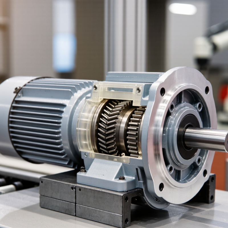
A precision gear motor combines an electric motor with a reduction gearbox. The motor creates rotational force, while the gearbox controls speed and increases usable torque. Inside the motor, copper windings and permanent magnets produce electromagnetic rotation. The rotor turns the gearbox through a shaft and coupling.

The gearbox contains carefully matched gears, bearings, and a lubricated housing. Each gear stage reduces speed and improves torque control. Planetary, spur, or helical gears may be used, depending on load and noise requirements. Bearings support rotating shafts and limit unwanted movement. The housing keeps the gears aligned and protects them from dust. A small error here can create noticeable backlash.

An encoder may monitor shaft position and speed. Its feedback helps a controller correct movement during repeated operations. This matters in robotic joints, medical equipment, and automated inspection systems. However, an encoder cannot fix poor mechanical alignment. That point is sometimes overlooked.

Tips: Check rated torque, output speed, backlash, and duty cycle together. Do not select a motor by torque alone. Measure starting loads carefully. Keep the gearbox properly lubricated, but avoid excess grease. During testing, listen for clicking, vibration, or uneven rotation. These details often reveal wear before failure.

How Torque and Motion Are Transmitted Step by Step

A precision gear motor combines an electric motor with a carefully manufactured gearbox. The motor creates rotational force at its shaft. A small pinion gear then drives a larger gear. This reduces speed and increases usable torque.

Torque and motion travel through several controlled steps. The input gear turns the next gear through meshing teeth. Each contact transfers force while changing speed, direction, or both. Multiple gear stages create the required reduction ratio. For example, a fast motor rotation may become a slower shaft rotation with stronger output force. Bearings support the shafts and limit unwanted movement. Lubrication reduces friction and protects the tooth surfaces. However, no system is perfectly rigid. Backlash, tooth wear, and slight shaft deflection can affect positioning accuracy. Efficiency also falls as more stages and friction points are added.

Tips: Match the motor’s rated torque with the real load, not only the catalog value. Include startup force, shock loads, and duty cycles. Check the output speed under load. A gearbox may appear accurate without resistance, then lose precision during operation. Measure backlash when the mechanism changes direction. Keep alignment exact, because a small offset can create noise, heat, and premature wear. Encoder feedback can improve control, but it cannot correct poor mechanical assembly.

What Is a Precision Gear Motor and How Does It Work?

A precision gear motor combines an electric motor with a reduction gearbox. The gearbox reduces speed and increases output torque. The chart shows calculated output torque for a motor producing 0.10 N·m at 3,000 rpm, using typical efficiency assumptions for different reduction ratios.

How torque and motion are transmitted:
  1. The motor generates rotational torque at high speed.
  2. The input gear drives progressively larger gears inside the gearbox.
  3. The reduction ratio lowers output speed: output speed = motor speed ÷ gear ratio.
  4. Gear reduction increases torque: output torque = motor torque × gear ratio × efficiency.
  5. Precision bearings, gear alignment, and controlled backlash help transfer motion accurately.

The values shown are engineering calculations based on the stated motor conditions and assumed gearbox efficiencies; they do not represent any specific manufacturer or brand.

Key Factors That Determine Precision and Performance

What Is a Precision Gear Motor and How Does It Work?

Key Factors That Determine Precision and Performance

A precision gear motor combines an electric motor, reduction gears, bearings, and feedback. The motor creates speed and torque. The gearbox trades speed for controlled output motion. An encoder reports shaft position, while a controller corrects error. In a machine, this may move a gripper two millimeters repeatedly, without visible hesitation.

Precision starts with backlash. Backlash is the lost motion between mating teeth. Lower values improve positioning, but they can increase friction and cost. Torsional stiffness matters when a load changes suddenly. Bearing clearance, gear geometry, lubrication, and assembly alignment also shape repeatability. Thermal growth is easy to overlook. A warm gearbox may shift its output position after hours of cycling. Encoder resolution helps, but it cannot repair a flexible shaft. I have seen specifications look excellent until the motor met real shock loads. That is the uncomfortable part.

According to the International Federation of Robotics’ World Robotics 2024 report, factories installed 541,302 industrial robots in 2023. Such scale makes repeatable motion valuable, not merely attractive. The U.S. Department of Energy’s Industrial Decarbonization Roadmap states that motor-driven systems consume roughly 70% of U.S. industrial electricity. A small efficiency loss can become a serious operating cost. Engineers should test loaded torque, temperature rise, backlash, and positioning error together. ISO 9283 offers accuracy and repeatability testing methods, but gear motors still need application-specific validation. A datasheet is only a starting point.

Common Applications and Selection Considerations

What Is a Precision Gear Motor and How Does It Work?

A precision gear motor combines an electric motor with a reduction gearbox. The gearbox lowers speed and increases usable torque. It also improves controlled movement. In practical machinery, this balance matters more than maximum motor speed. A small shaft may need to stop within a fraction of a millimeter. That is where gear accuracy, backlash, and feedback become important.

Common applications include robotic joints, conveyor indexing systems, medical equipment, packaging machines, and camera positioning devices. These systems often require repeatable starts and stops. A motor for a conveyor may prioritize continuous torque and low heat. A motor for a robotic axis may need fast response, low backlash, and an encoder. The application decides the design.

Selection should begin with load torque, operating speed, duty cycle, and required positioning accuracy. Check the gearbox ratio carefully. A higher ratio increases torque but can reduce output speed. Also consider shock loads, noise, mounting space, and ambient temperature. Sealing becomes important in dusty or humid workplaces. Electrical compatibility matters too, including voltage, current, control method, and feedback signals.

A clean calculation can still fail in the workshop. Alignment errors, cable drag, and unexpected starts affect performance. I would test the motor under real load, not only on a bench. Leave some torque margin, but avoid excessive oversizing. It can waste energy and make motion less responsive. Selection is rarely perfect on the first attempt. Practical measurements should challenge the original assumptions.

What Is a Precision Gear Motor and How Does It Work? - Common Applications and Selection Considerations

A precision gear motor combines an electric motor with a gear reducer to provide controlled speed, increased output torque, and improved positioning capability. The ranges below are typical engineering values and can vary according to motor size, gear geometry, lubrication, load, temperature, and operating conditions.

Data Dimension Typical Value or Principle How It Works Common Applications Selection Considerations
Basic Definition Electric motor plus an integrated precision gearbox The motor produces rotational power, while the gearbox reduces speed and increases usable output torque. The gear train also helps match the motor's operating speed to the driven mechanism. Automated machinery, robotics, conveyors, medical equipment, laboratory instruments, and compact positioning systems Confirm the required output speed, continuous torque, peak torque, duty cycle, mounting arrangement, and allowable shaft load.
Operating Principle Mechanical speed reduction through meshing gears When the input gear drives a larger output gear, output speed decreases while torque increases. The approximate ideal relationship is: Output Speed = Motor Speed ÷ Reduction Ratio. Applications requiring stable low-speed rotation or controlled linear movement Include gearbox efficiency when estimating output torque: Output Torque ≈ Motor Torque × Reduction Ratio × Efficiency.
Typical Motor Speed Approximately 1,000–4,000 rpm for many small and medium electric motors Motors generally operate efficiently at relatively high speed. The gearbox converts this speed into a lower speed suitable for the application. Actuators, dosing mechanisms, compact drives, valve systems, and automated adjustment devices Choose a motor speed compatible with the required reduction ratio, thermal limits, control method, and noise requirements.
Common Reduction Ratios Approximately 3:1 to 500:1 in practical multi-stage arrangements Higher ratios are normally achieved by using multiple gear stages. Each additional stage can increase torque capacity but may reduce efficiency and increase size. Low-speed conveyors, rotary tables, robotic joints, lifting mechanisms, and positioning systems Avoid selecting an unnecessarily high ratio because it may increase backlash, losses, size, and response time.
Output Speed Often below 1 rpm to several hundred rpm, depending on the motor and ratio Output speed is determined by motor speed, reduction ratio, gearbox efficiency, and the control system's commanded speed. Indexing equipment, inspection machines, turntables, feeders, and slow-moving actuators Specify both nominal speed and the required speed range. Check whether the motor can operate continuously at the requested low speed without overheating.
Output Torque From a fraction of a newton-metre to several hundred newton-metres, depending on frame size and design Torque is multiplied by the reduction ratio, but friction, gear losses, bearing load, and thermal limits reduce the usable value. Material handling, automated clamps, robotic axes, lifting devices, and rotary positioning systems Separate continuous torque from peak or acceleration torque. Apply an appropriate service factor for shock loads, starts, stops, and variable loading.
Spur or Helical Gearbox Typical efficiency: approximately 80–95%; moderate to low backlash depending on design Spur gears use straight teeth, while helical gears use angled teeth. Helical gears generally provide smoother and quieter engagement but create axial thrust. Conveyors, packaging machinery, automated feeders, general-purpose actuators, and industrial mechanisms Consider efficiency, noise, axial-load capability, lubrication, operating speed, and the required positioning accuracy.
Planetary Gearbox Typical efficiency: approximately 90–97%; low backlash designs may reach below 10 arcminutes Multiple planet gears share the load between a central sun gear and an outer ring gear. This produces high torque density and good load distribution. Robotic joints, servo axes, machine tools, automation equipment, and compact high-torque drives Useful when high torque, compact size, low backlash, and good torsional stiffness are important. Verify bearing capacity and permissible radial loads.
Worm Gearbox Typical efficiency: approximately 40–90%, depending on ratio, lubrication, and geometry A worm screw drives a worm wheel. The design can provide large reduction ratios in a compact housing and may offer resistance to reverse driving at certain ratios. Gates, lifts, conveyors, rotary tables, adjustment mechanisms, and applications needing high reduction in limited space Check heat generation, efficiency, duty cycle, back-driving behavior, lubrication, and whether self-locking can be relied upon for safety.
Harmonic or Strain-Wave Gearbox Typical backlash: often below 1 arcminute in precision configurations; efficiency commonly around 70–90% A flexible spline, circular spline, and wave generator create high reduction in a compact package with very low backlash and high positioning repeatability. Robotic joints, optical equipment, semiconductor machinery, and compact precision positioning systems Evaluate torsional stiffness, permissible shock load, bearing capacity, lifetime under reversing motion, and continuous versus peak torque.
Backlash Approximately less than 1 to 30 arcminutes, depending on gearbox type and precision class Backlash is the angular clearance between mating gear teeth. It can cause lost motion when the direction of rotation changes. Low-backlash requirements are common in robotics, CNC equipment, optical systems, and precision indexing Specify maximum allowable backlash at the output shaft. Consider temperature, wear, load direction, and the effect of couplings or flexible components.
Positioning Accuracy and Repeatability Determined by backlash, encoder resolution, torsional deflection, controller performance, and load compliance The gearbox reduces speed and may improve controllability, but it cannot independently guarantee positioning accuracy. Feedback and mechanical stiffness are also required. Pick-and-place systems, automated inspection, dosing, indexing, and robotic motion control Define accuracy, repeatability, settling time, and allowable overshoot separately. Select the encoder location and resolution accordingly.
Efficiency Approximately 40–97%, depending mainly on gearbox type, ratio, speed, and load Power is lost through tooth friction, bearing friction, seal drag, lubricant resistance, and motor losses. Higher efficiency generally reduces heat generation. Battery-powered equipment, continuously operating conveyors, mobile machinery, and energy-sensitive systems Use measured efficiency at the actual operating point when possible. Check thermal performance rather than relying only on nominal motor power.
Duty Cycle Continuous, intermittent, cyclic, or short-time operation Motor and gearbox temperature depends on running time, load profile, start frequency, ambient temperature, and cooling conditions. Continuous conveyors, cyclic actuators, door mechanisms, medical instruments, and battery-operated products Provide the full motion profile: running time, rest time, acceleration, deceleration, load torque, and number of starts per hour.
Motor Control Open-loop control, closed-loop encoder control, or servo control A controller regulates voltage, current, frequency, or position. Feedback from an encoder can compensate for speed variation and improve positioning performance. Speed-controlled fans, automated actuators, robotic axes, dosing systems, and synchronized machinery Select feedback based on required accuracy and load variation. Confirm compatibility among motor, drive, encoder, braking system, and controller.
Environmental Protection Ingress protection commonly ranges from basic enclosed designs to high-protection housings Seals, housing design, connectors, and coatings protect the motor and gearbox from dust, moisture, cleaning fluids, and other contaminants. Outdoor equipment, food-processing machinery, washdown areas, laboratory devices, and dusty industrial environments Specify ambient temperature, humidity, dust, water exposure, chemical contact, mounting orientation, and required ingress protection level.
Mounting and Shaft Loads Must be matched to permissible radial, axial, and moment loads External loads are transferred through the output shaft and gearbox bearings. Excessive overhung or axial loads can shorten service life or cause premature failure. Belts, pulleys, sprockets, gears, lead screws, and directly coupled mechanisms Calculate radial and axial forces, check shaft diameter and keyway requirements, and use an external support bearing when necessary.
Noise and Vibration Generally lower with helical, planetary, and precision-finished gear designs than with basic spur designs Noise and vibration are affected by tooth geometry, manufacturing accuracy, lubrication, bearing condition, imbalance, and mounting stiffness. Office automation, medical devices, laboratory equipment, cameras, and indoor consumer machinery Define acceptable sound pressure, vibration, and resonance limits. Evaluate the complete drive assembly, not only the motor and gearbox.
Recommended Selection Sequence Load → speed → torque → duty cycle → accuracy → environment → mechanical interface A systematic process prevents undersizing and avoids selecting a gearbox based only on nominal motor power. Nearly all engineered gear motor applications Calculate required torque and speed, apply service factors, verify thermal capacity, check backlash and stiffness, then confirm dimensions, controls, and lifetime.

FAQS

What is a precision gear motor?

It combines an electric motor, reduction gears, bearings, and feedback. The motor produces motion. The gearbox reduces speed and increases usable torque. An encoder reports shaft position to a controller. This helps a gripper move two millimeters repeatedly.

How does feedback improve positioning?

An encoder measures shaft position during operation. The controller compares the actual position with the target. It then corrects the difference. Feedback improves repeatability, but it cannot fix every mechanical weakness.

Why is backlash important?

Backlash is lost movement between mating gear teeth. Lower backlash usually improves positioning accuracy. However, tighter gears can increase friction, noise, and cost. The best value depends on the application. Perfectly low backlash is not always necessary.

Which factors affect precision besides backlash?

Torsional stiffness, bearing clearance, gear geometry, lubrication, and alignment all matter. A flexible shaft may twist under sudden load. A loose bearing can create inconsistent movement. Small assembly errors can become visible at the output shaft.

Can temperature change positioning accuracy?

Yes. A gearbox may become warm after hours of cycling. Its parts can expand slightly. The output position may then shift. Testing only at room temperature can create false confidence.

What should engineers check when selecting a gear motor?

Check load torque, operating speed, duty cycle, and positioning accuracy. Also review the gear ratio, shock loads, noise, and mounting space. Dust and humidity may require better sealing. Voltage, current, control method, and feedback signals must match.

Where are precision gear motors commonly used?

Common uses include robotic joints, conveyor indexing, medical equipment, packaging machines, and camera positioning. A conveyor may need steady torque and low heat. A robotic axis may need rapid response and low backlash. The machine decides the priority.

How should a gear motor be tested?

Test it under the real load, not only on a clean bench. Measure torque, temperature rise, backlash, and positioning error together. Include sudden load changes and repeated starts. Cable drag and alignment errors can matter. My initial calculation may still be wrong.

Is a higher gear ratio always better?

No. A higher ratio usually increases output torque. It also reduces output speed. The motor may become less responsive during quick movements. Choose enough torque margin without excessive oversizing. More capacity can waste energy.

What makes a datasheet insufficient?

A datasheet usually describes controlled conditions. Real machines add heat, vibration, shock loads, cable resistance, and alignment errors. Testing standards can guide accuracy and repeatability checks. Application-specific validation remains necessary. Reality sometimes disagrees.

Conclusion

A Precision Gear Motor is an integrated drive system designed to deliver controlled speed, reliable torque, and accurate motion in compact mechanical equipment. It combines an electric motor with a gearbox that reduces rotational speed while increasing torque, allowing machines to move loads smoothly and consistently. Its main components typically include the motor, gears, shafts, bearings, housing, and control elements. Each part contributes to efficient power transmission, stability, and long service life.

During operation, electrical energy creates rotation in the motor, which passes through successive gear stages. The gears adjust speed and torque, while shafts transfer the resulting motion to the output mechanism. Precision and performance depend on gear quality, manufacturing tolerances, lubrication, alignment, motor capacity, backlash, and thermal management. These motors are commonly used in robotics, automation equipment, medical devices, positioning systems, and compact machinery. When selecting one, users should consider required torque, speed, accuracy, operating environment, noise level, dimensions, duty cycle, and control compatibility to ensure dependable performance.

Ethan

Ethan

Ethan is a seasoned marketing professional with a deep expertise in our company's innovative product line. With a passion for sharing knowledge and insights, he takes the lead in regularly updating our corporate blog, where he explores industry trends, product features, and effective marketing......