RACB Motor
A Cylindrical Gear Motor can turn a compact electric drive into controlled, usable torque for conveyors, mixers, packaging lines, and other industrial equipment. Its inline arrangement can simplify installation where space is limited, while the gear stage reduces speed and increases output torque. The result is practical, but not automatic.
Energy use makes motor selection worth careful attention. The U.S. Department of Energy’s Improving Motor and Drive System Performance: A Sourcebook for Industry reports that motor-driven systems account for about 54% of electricity use in U.S. manufacturing. That figure describes motor systems broadly, not cylindrical gear motors alone. Still, it highlights why efficiency, correct sizing, and operating conditions matter. A gearbox chosen only by its nameplate rating may perform poorly under frequent starts, shock loads, or long daily run times.
This guide examines where cylindrical gear motors fit, how to compare torque, speed, efficiency, and mounting options, and what to check before purchase. Look beyond catalogue claims: confirm the load profile, duty cycle, ambient conditions, and required service life with the supplier. Small details matter. A slightly mismatched ratio can mean slower throughput, extra heat, or avoidable maintenance. And one limit deserves attention: no single gear motor suits every machine. The right choice depends on the application, not just the product description.
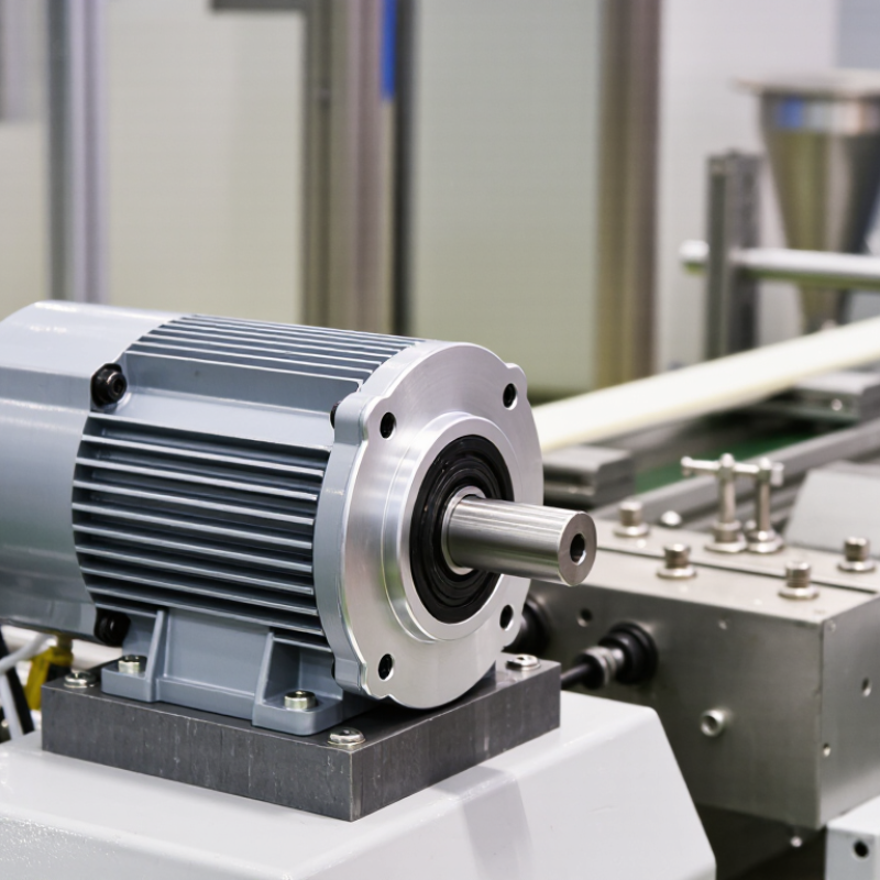
A cylindrical gear motor combines an electric motor with a cylindrical, usually helical, gearbox. Its compact inline layout suits conveyors, mixers, and packaging equipment where steady torque and predictable speed matter. But what does IEC 60034-30-1 actually define? It sets IE energy-efficiency classes for specified types of AC motors, not for the complete gear motor assembly.
That distinction matters. The motor’s eligible efficiency class depends on its design and rated operating conditions; the gearbox has its own mechanical losses. An IE label on the motor therefore does not describe the combined unit’s total efficiency. Check the motor nameplate and technical data, then compare gearbox ratios, output speed, and required torque. A practical check is to measure the driven machine’s load, rather than selecting from rated power alone. Small oversights matter.
For example, a motor may meet an IE class while the selected ratio causes the process to run inefficiently. Installation, cooling, supply conditions, and duty cycle can also affect real-world energy use. IEC classification offers a useful comparison, but it cannot replace application-specific sizing. That is easy to overlook, even with a clear datasheet.
| Why Choose a Cylindrical Gear Motor? — What Defines a Cylindrical Gear Motor Under IEC 60034-30-1? | ||
|---|---|---|
| Dimension | What It Means | Practical Consideration |
| Basic definition | A cylindrical gear motor is an electric motor combined with a cylindrical gearbox, commonly using helical gears to transmit power between parallel shafts and reduce speed. | It provides lower output speed and higher output torque than the motor alone. Actual output depends on the motor, gear ratio, and gearbox rating. |
| Meaning of “cylindrical” | The term describes the gear type and tooth geometry, rather than an efficiency class or a specific IEC motor designation. | Helical cylindrical gears typically engage gradually, which can support smooth operation. Gear design, lubrication, mounting, and loading affect performance. |
| What IEC 60034-30-1 covers | This standard defines IE efficiency classes for specified single-speed, three-phase, cage-induction motors. It does not define cylindrical gear motors as a gearbox category. | Check whether the motor itself is within the standard’s scope before using its IE classification. |
| IE efficiency classes | The standard includes IE1 (Standard Efficiency), IE2 (High Efficiency), IE3 (Premium Efficiency), and IE4 (Super Premium Efficiency). | Compare the motor’s declared class and efficiency at the relevant rating. The required efficiency depends on motor output, pole count, frequency, and applicable regulations. |
| Motor scope factors | Scope depends on characteristics including rated output, number of poles, supply frequency, voltage, and operating duty. The standard covers defined motor ranges and configurations. | Do not assume every motor used in a gear motor assembly qualifies. Confirm the motor nameplate and manufacturer’s technical documentation against the applicable edition. |
| Motor efficiency versus assembly efficiency | An IE class describes the covered motor’s efficiency; it is not, by itself, an efficiency rating for the combined motor-and-gearbox assembly. | Gearbox losses reduce the power delivered at the output shaft. For system comparisons, consider motor efficiency, gearbox efficiency, operating point, and duty cycle together. |
| Speed and torque | The gearbox reduces motor speed according to its ratio and increases available output torque, subject to losses and mechanical limits. | Confirm required output speed, continuous and peak torque, service factor, starts per hour, and any braking or back-driving requirements. |
| Mounting and shaft layout | Cylindrical gear units are commonly selected for parallel-shaft arrangements and may be supplied in different mounting positions and shaft configurations. | Check installation space, shaft orientation, mounting position, terminal-box access, and permissible radial and axial loads. |
| Selection checklist | Specify the driven load, required output speed and torque, supply conditions, operating hours, ambient conditions, and installation constraints. | Request separate motor and gearbox ratings, efficiency information, thermal limits, and any applicable compliance declarations. |
| Standards note | IEC 60034-30-1 is an efficiency-classification standard for covered motors; it does not replace gearbox performance specifications or local energy regulations. | Verify the applicable standard edition and regulatory requirements for the installation location and equipment configuration. |
It defines energy-efficiency classes for specified AC motors. It does not classify the complete gear motor assembly.
No. The gearbox has mechanical losses, so the motor’s label does not show combined efficiency. Check both motor and gearbox data.
One well-lubricated mesh may reach roughly 97–98% efficiency under suitable conditions. That figure is not for the entire unit.
Alignment, oil viscosity, temperature, load, bearings, and seals all matter. Small losses add up.
A 1,500 rpm input gives about 150 rpm in a simple calculation. Actual speed may be lower under load.
From a 1,500 rpm input, the estimated output is near 50 rpm. Gear losses and motor slip affect the result.
No. It may slow a conveyor too much or create extra heat under a heavy, continuous load. Check the actual duty.
Compare required speed, torque, load, duty cycle, ratio, and gearbox efficiency. Measure the loaded output speed if possible; paper calculations can miss real conditions.
A Cylindrical Gear Motor combines an electric motor with cylindrical gears to deliver controlled speed and increased output torque. IEC 60034-30-1 provides efficiency classes for motors, helping users assess the motor component alongside the gearbox’s performance. Helical gear meshes can typically achieve around 97–98% efficiency under suitable operating conditions, while the selected gear ratio determines how much speed is reduced. For example, a 1,500 rpm, 4-pole motor paired with a 15:1 reduction produces an output speed of approximately 100 rpm.
Reliable selection also depends on gear strength and the demands of the application. ISO 6336 methods assess tooth-root bending strength and surface contact durability, supporting design decisions for expected loads and service life. Multi-stage cylindrical gear motors are suited to industrial equipment that needs compact, dependable speed reduction and steady torque, including conveyors, mixers, and material-handling systems.