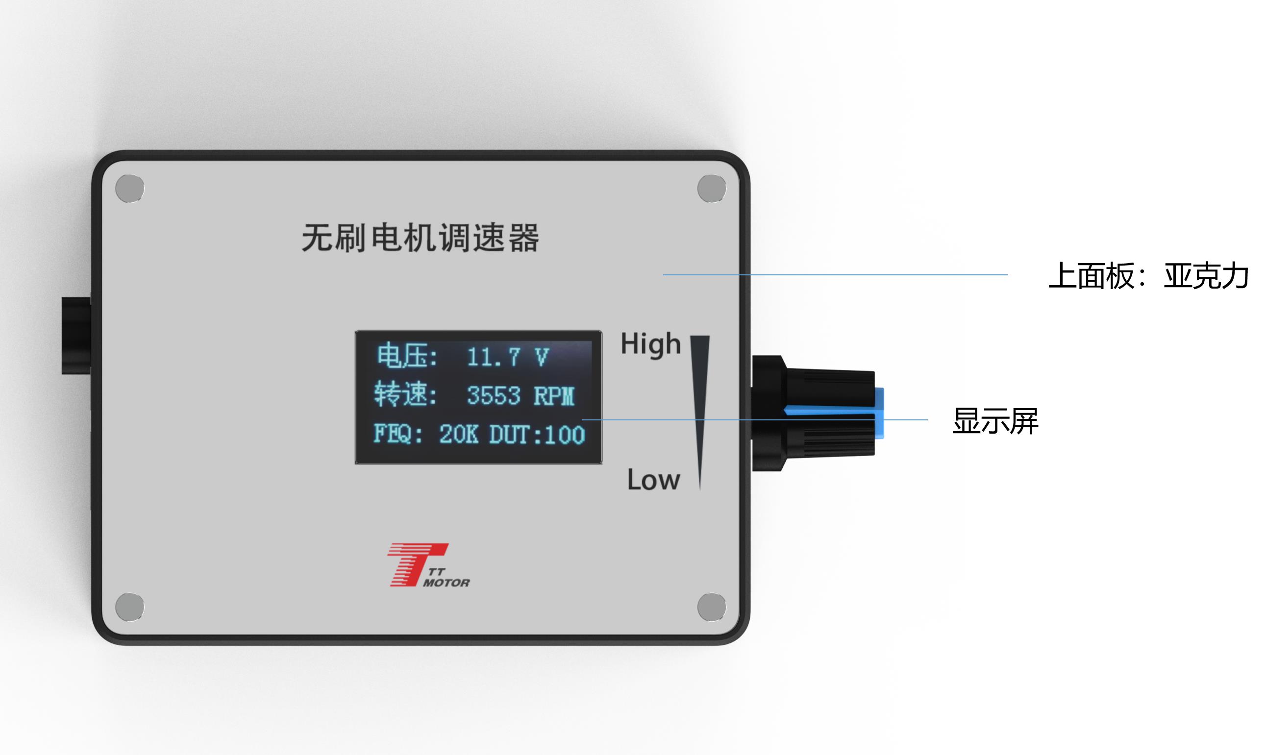
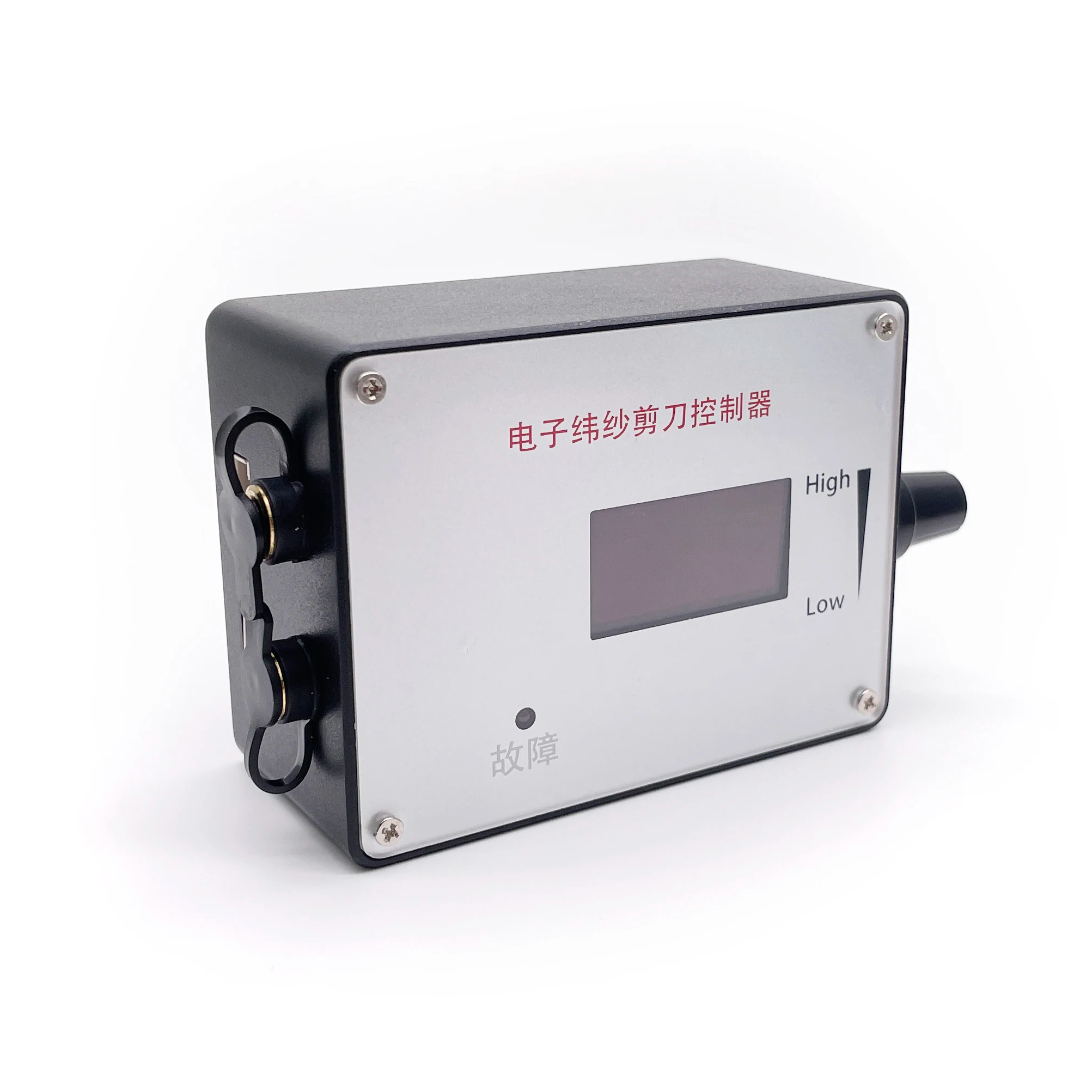
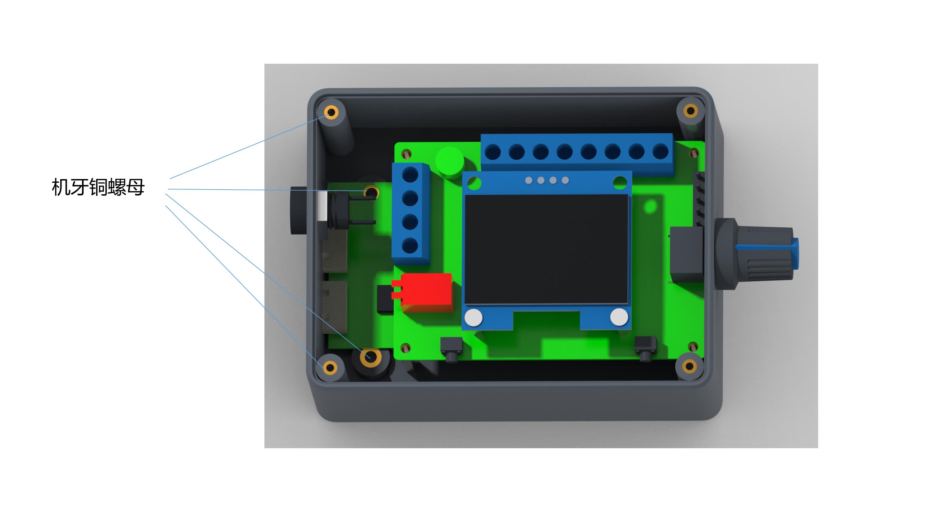
🔌 2. Governor Wiring and Internal Function Description
- 1Governor, motor power supply positive input.
- 2Governor, motor power input negative.
- 3The positive output of the power supply of the motor.
- 4Negative output of the power supply of the motor.
- 5High and low level output of positive and negative rotation control (high level 5V, low level 0V, controlled by touch switch 2 (F/R), default is high level).
- 6High and low level output of brake control (high level 5V, low level 0V, controlled by touch switch 1 (BRA), power on default high level).
- 7Analog voltage output (0~5V): This interface is suitable for accepting analog voltage speed regulation motor.
- 8PWM1 reverse output: This interface is suitable for the motor that accepts PWM speed regulation, and the speed is inversely proportional to the duty cycle.
- 9PWM2 forward output: This interface is suitable for motors that accept PWM speed regulation, the speed is proportional to the duty cycle.
- 10The output signal changes of the 7, 8, 9 interfaces are adjusted by the potentiometer.
- 11Motor feedback signal input.
💡 Feedback & Direction Settings Notice:
FG/FG*3: Should be based on the actual motor feedback times whether to add a jumper cap. No jumper cap is a single times FG, increased jumper cap is 3 times FG*3.
CW/CCW: Same rule applies for configuring motor rotation direction settings.
❓ Frequently Asked Questions (FAQ)
What is the working voltage and maximum current of this governor?
The voltage range of the governor is DC5V-28V, and the rated current is MAX 2A. If you need to control a motor with higher current requirements, the motor power line must be connected directly to the power supply instead of passing through the governor.
How do I change the frequency settings of the driver board?
Before powering on, press and hold the touch switch 1, then apply power. Release the button once "FEQ:20K" appears on the screen. You can then use touch switch 1 to decrease the frequency and touch switch 2 to increase it. The factory default value is 20KHz.
How do I set the number of poles for my motor?
Press and hold both touch switch 1 and touch switch 2 simultaneously before powering on. Connect the power and release the buttons when the screen displays "number of poles: 1 polarity". Use touch switch 1 to reduce and touch switch 2 to increase to match your motor's design.
What happens if I reverse the positive and negative power supply connections?
You must follow the wiring instructions carefully. Reversing the positive and negative power inputs will prevent the governor from operating and will burn out the internal circuitry.
Can I apply more than 5V to the control ports?
No, the control ports (specifically the five ports designated from 5 to 9) cannot accept any voltage input that exceeds 5V. Doing so may damage the control interfaces.
 RACB Motor